How to run FEST-3D solver?
Steps to run FEST-3D
Once you have downloaded and installed the FEST-3D code, you are ready to use the FEST-3D solver. A step by step guide for the LiD-Driven cavity is given on this page.
Run folder
First, change the current directory to run/ directory. Now check if run/ directory is empty or it already has files in it. Use:
$ls
If run/ folder is empty, that means the submodule run has not been download. You should use the following command to get all the files:
$git submodule update --init
The $ls command in run/ directory should show the following file/folder name as output:
edit-automaton.py README.md Tutorials/
Sample edit-automaton.py script
The edit-automaton.py in the run directory is a sample script file. This script file is not supposed to be executed as the inputs are randomly provided as an explanation for the variables. Users are supposed to copy this script and modify as according to need. In the Tutorial/ subfolder, different edit-automaton.py file is provided with specific inputs.
README.md
This markdown file contains information about:
- Software dependencies of run module
- Information about all the input variables in edit-automaton.py
- Directory structure created for each test case.
- How to start the simulation once setup for the test case is done.
Tutorial
Few test cases are provided in Tutorials/ folder for learning and verification purpose.
Generate Grid before executing edit-automaton.py script
For all the tutorial, a grid file is provided in CreateBlocks/ subfolder. You can generate the grid by just changing directory to CreateBlocks/ subfolder, and type following make command:
$make
It will create a grids/ subfolder in CreateBlocks. In the grid/ multiple grid files are written, one for each processor. For each tutorial, an input is provided for the number of processors to be used for the simulation. Except for 2D bump test case, the number of blocks in i,j,k direction can be changed in blocking_point.f90 file at:
  integer, parameter :: xblocks = 4
  integer, parameter :: yblocks = 1
  integer, parameter :: zblocks = 1
It should be noted that the grid generation process is not part of the FEST-3D solver and has to be handled separately. You can write your code for grid-generation of simple geometries. An example for such code is bump.py python script for 2D smooth bump grid generation. You can also use software like pointwise for complicated geometries.
Modify and execute edit-automaton.py
edit-automaton.py script is provided in each tutorial folder. Although most of the input in the edit-automaton.py has been set according to the test case, you still need to change the first few lines of this file:
RunDir = 'GiveAnyName'
GridDir= 'PathToAllGridFiles'
NumberOfBlocks = 4 #Make sure it is same as the number of grid-files
If you are not able to run or set up the test case, then the above lines in the edit-automaton.py may be the culprit. You can give any name for RunDir. A new folder will be created with the name you supply here. You can give a different name for a different version for the input you give in edit-automaton.py. For GridDir variable provide folder name in which all the grid files are present. For all the tutorials, grid files created are situated at "CreateBlocks/grids". For NumberOfBlocks provide the number of processors you want to use for the simulation. Make sure the NumberOfBlocks and number of grid files in GridDir are the same. This will be asserted in the latter part of the script. If this is not the case following error will be thrown:
ERROR:
Traceback (most recent call last):
  File "edit-automaton.py", line 340, in <module>
    CheckInput(ExpectedControl, ExpectedScheme, ExpectedFlow, ExpectedOutputControl, ExpectedResidualControl, Control, Scheme, Flow, OutputControl, ResidualControl)
  File "edit-automaton.py", line 183, in CheckInput
    assert len(next(os.walk(GridDir))[2]) == NumberOfBlocks
StopIteration
Same error will be shown if the folder name provided for GridDir is invalid.
Steps to run Lid-Driven Cavity tutorial
- Make sure the run directory has the Turtorial folder.
- Change directory to the FEST-3D/run/Tutorials/LidDrivenCavity/. This folder contains edit-automaton.py file and CreateBlocks/ subfolder
-
Change directory to CreateBlocks/ subfolder and open blocking_point.f90. Change number of I-direction blocks and J-direction blocks to what you desire. Do not change the K-direction blocks as there is only one cell in the third direction.
  integer, parameter :: xblocks = 2
  !< Number of block in I-directions
  integer, parameter :: yblocks = 2
  !< Number of block in J-directions
  integer, parameter :: zblocks = 1
  !< Number of block in Z-directions
-
A makefile is provided to automate the grid generation and blocking process. Use the following command to generate the grid/ folder which contains all the grid files.
$make
An important point to note here is that the grid generation requires numpy version 1.10 or above for Python2.7
-
Once the grids are generated, go one-directory up to run/Tutorials/LidDrivenCavity/.
-
Open edit-automaton.py and change first three variables:
RunDir = 'LDC-Test1'
GridDir= 'CreateBlocks/grid'
NumberOfBlocks = 4 #Make sure it is same as the number of grid-files
-
Run the python script
python edit-automaton.py
If you have provided a wrong path to grid files or incorrect number of blocks to use, you will get the following error:
ERROR:
Traceback (most recent call last):
  File "edit-automaton.py", line 340, in <module>
    CheckInput(ExpectedControl, ExpectedScheme, ExpectedFlow, ExpectedOutputControl, ExpectedResidualControl, Control, Scheme, Flow, OutputControl, ResidualControl)
  File "edit-automaton.py", line 183, in CheckInput
    assert len(next(os.walk(GridDir))[2]) == NumberOfBlocks
StopIteration
If not error occured, a new folder: LDC-Test1 will be generated.
-
Change to newly created folder LDC-Test1. You will find the following directory structure: bin/ fill_vtk_name.sh gnplt pp/ pre/ run.sh system/ time_directories/
- bin/ soft link to FEST-3D binary resides in this folder.
- gnplt is GNUPLOT script to live plot the residual while a simulation is running in the background.
- pp/ and pre/ are the directories to keep you pre-processing and post-processing code. Currently, they should be empty.
- run.sh is the bash script which will be executed. It contains the instruction to pipe all the screen output to the time_directories/aux/out file.
-
system/ contains the information about the grid, boundary condition, layout of blocks, and input and output configuration of current simulation.
- control.md contains information about all the control parameters like CFL, Maximum number of iteration, output file format, etc.
- fvscheme.md contains information about the numerical schemes to use for the current simulation.
- flow.md contains information about the flow: reference velocity, density, pressure, viscosity, etc.
- output_control.md contains the name of the variable to read or write to the solution file in the time_directories.
- res_control.md contains the name of the residual which you want to track.
-
mesh/ Contains information about the grid and its layout.
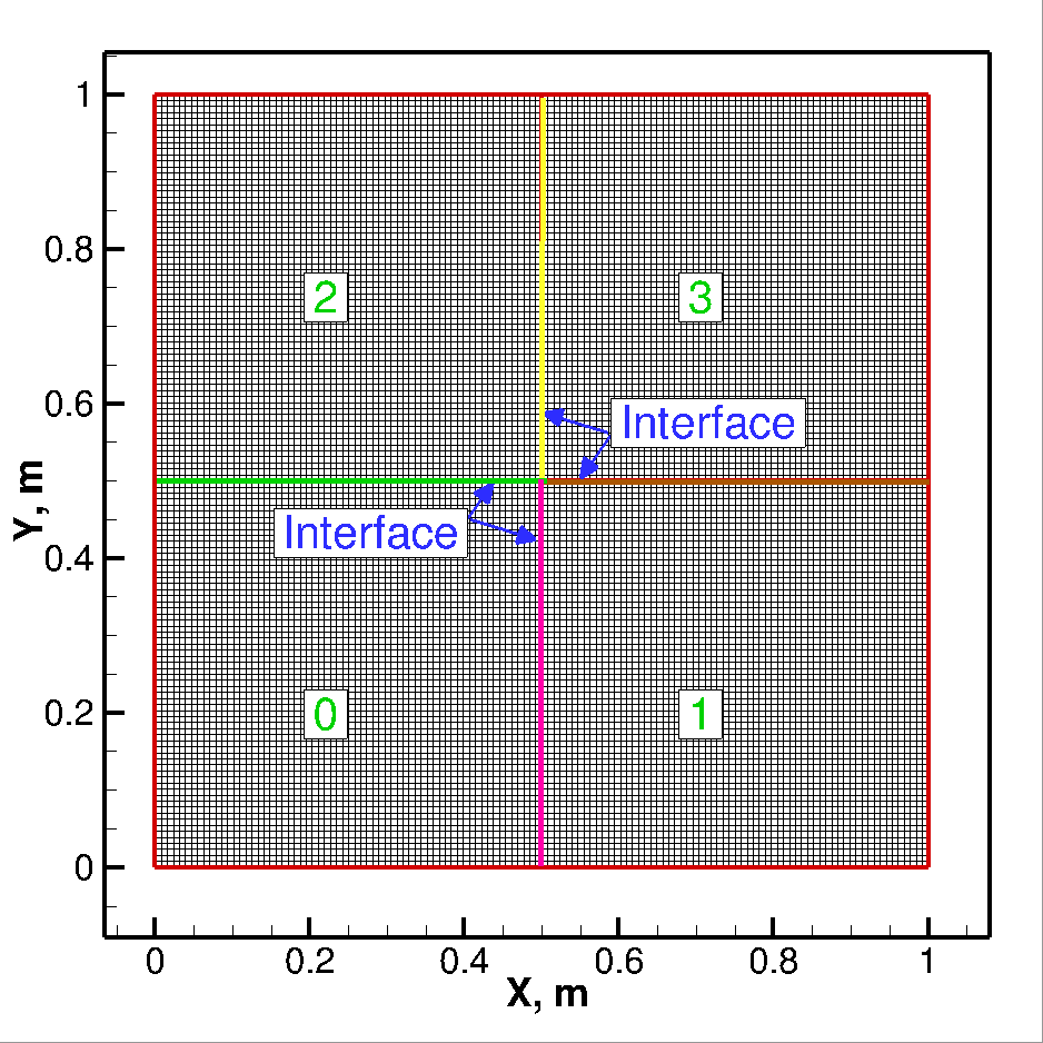
Fig.2 Domain and mesh decomposition in to 4 blocks. - Gridfiles/ Contains all the grid file used for the simulation
-
layout/ contains the information about the layout of the grid file and some script to most of the information about the layout automatically from the grid file in the Gridfiles/ folder.
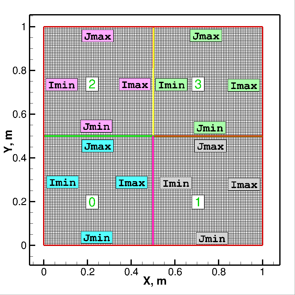
Fig.3 Boundary faces of each block indicated with 'Imin', 'Imax', 'Jmin', and 'Jmax' labels. -
layout.md file contains layout information. For more information about layout file check this page. The layout.md file should look like the following:
## BLOCK LAYOUT FILE
## ==========================
## NUMBER OF PROCESSES
4
## NUMBER OF ENTRIES PER PROCESS
9
## PROCESS_NO GRID BC_FILE IMIN IMAX JMIN JMAX KMIN KMAX
## ===================================
## PROCESS 0
00  grid_00.txt  bc_00.md  -005  0001  -005  0002  -006  -006
## PROCESS 1
01  grid_01.txt  bc_01.md  0000  -005  -005  0003  -006  -006
## PROCESS 2
02  grid_02.txt  bc_02.md  -005  0003  0000  -003  -006  -006
## PROCESS 3
03  grid_03.txt  bc_03.md  0002  -005  0001  -003  -006  -006
here the boundary condition numbers are as follow:
  * -1: Supersonic Inlet
  * -2: Supersonic Outflow
  * -3: Subsonic Inflow
  * -4: Subsonic Outflow
  * -5: Wall
  * -6: Symmetry or Slip-Wall
  * -7: Pole
  * -8: Far-field
  * -9: Total inlet
-
-
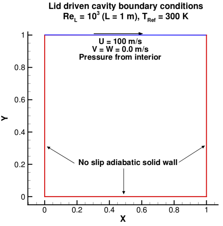
bc/ folder contains a separate boundary condition file for each block. In layout.md file you can fix the type of boundary but in bc_xx.md file you can give a particular value to the variable you want to fix. For Lid-Driven cavity test case, we need to fix velocity of the top lid. This can be done easily by opening the file of the block, which contains the lid, and set value of velocity to the boundary face, which represents the lid. Change
    # jmx
    - FIX_DENSITY
    - FIX_X_SPEED
    - FIX_Y_SPEED
    - FIX_Z_SPEED
    - COPY_PRESSURE
to
    # jmx
    - FIX_DENSITY
    - FIX_X_SPEED 100.0
    - FIX_Y_SPEED 0.0
    - FIX_Z_SPEED 0.0
    - COPY_PRESSURE
Fig.4. For lid-driven cavity a velocity vectory of (100,0,0) will be fixed at top boundary.
-
time_direcories/ contains a folder for each save point.
- aux/ contains the auxiliary files like
- out output of all the print command in the solver
- resnorm residual which you can plot using gnplt script
- surfacenode.dat : In case of turbulence model being used, this file is written to calculate wall-distance.
- aux/ contains the auxiliary files like
-
Finally, to run the simulation, use the following command:
$nohup bash run.sh &
nohuphelps in avoiding any output on the screen, & execute the last command in the background, allowing you to keep using the terminal. If you do not get any error, but still simulation terminates as soon it begins, run following command:$mpiexec.hydra -np 4 bin/FEST3D
it will provide output on the screen and help you debug.
-
You can use GNUPLOT to plot the residual using
$gnuplot gnplt
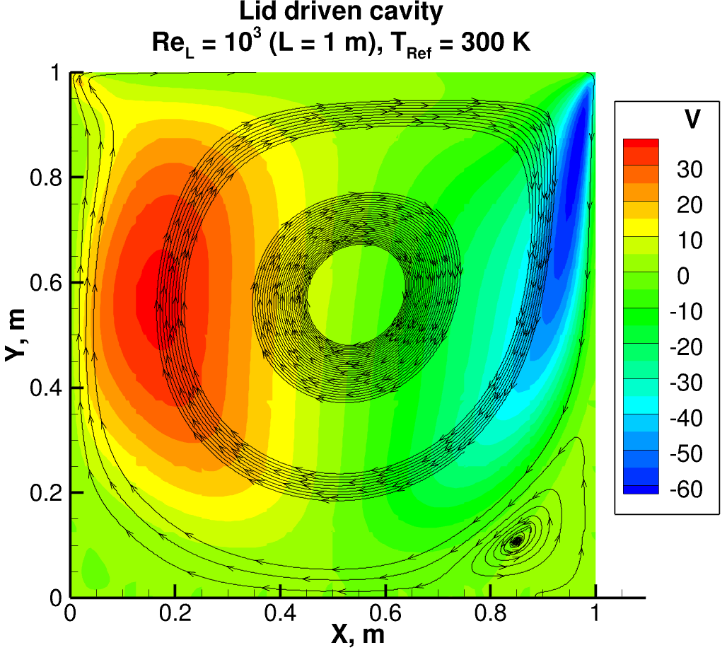
Results
Post-processing is not part of the FEST-3D solver. FEST-3D provides two output file formats: vtk and Tecplot, which you can specify in the edit-automaton.py file. You can use software like visit, paraview, Tecplot to visualize the obtained solution data from FEST-3D.