Layout file
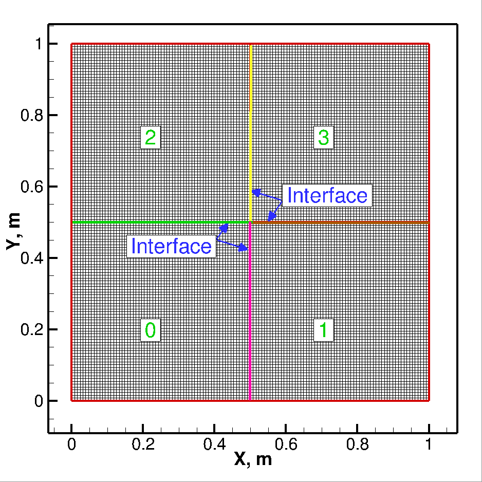
When performing a multi-block simulation, some information has to communicate between adjacent
blocks. For this process, a setup file is provide called layout.md in the system/mesh/layout
folder. This file contains information about the adjacent blocks and physical boundary conditions.
All the non-negative numbers in this file represent the interface boundary condition, and negative
numbers represent the physical boundary conditions. For each block/process a row of information is
written:
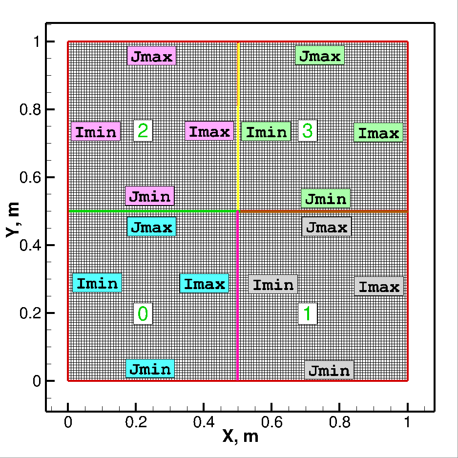
- Block number
- Grid file name in the system/mesh/gridfile/ directory
- Boundary condition file name in the system/mesh/bc/ directory
- Boundary condition at Imin face.
- Boundary condition at Imax face.
- Boundary condition at Jmin face.
- Boundary condition at Jmax face.
- Boundary condition at Kmin face.
- Boundary condition at Kmax face.
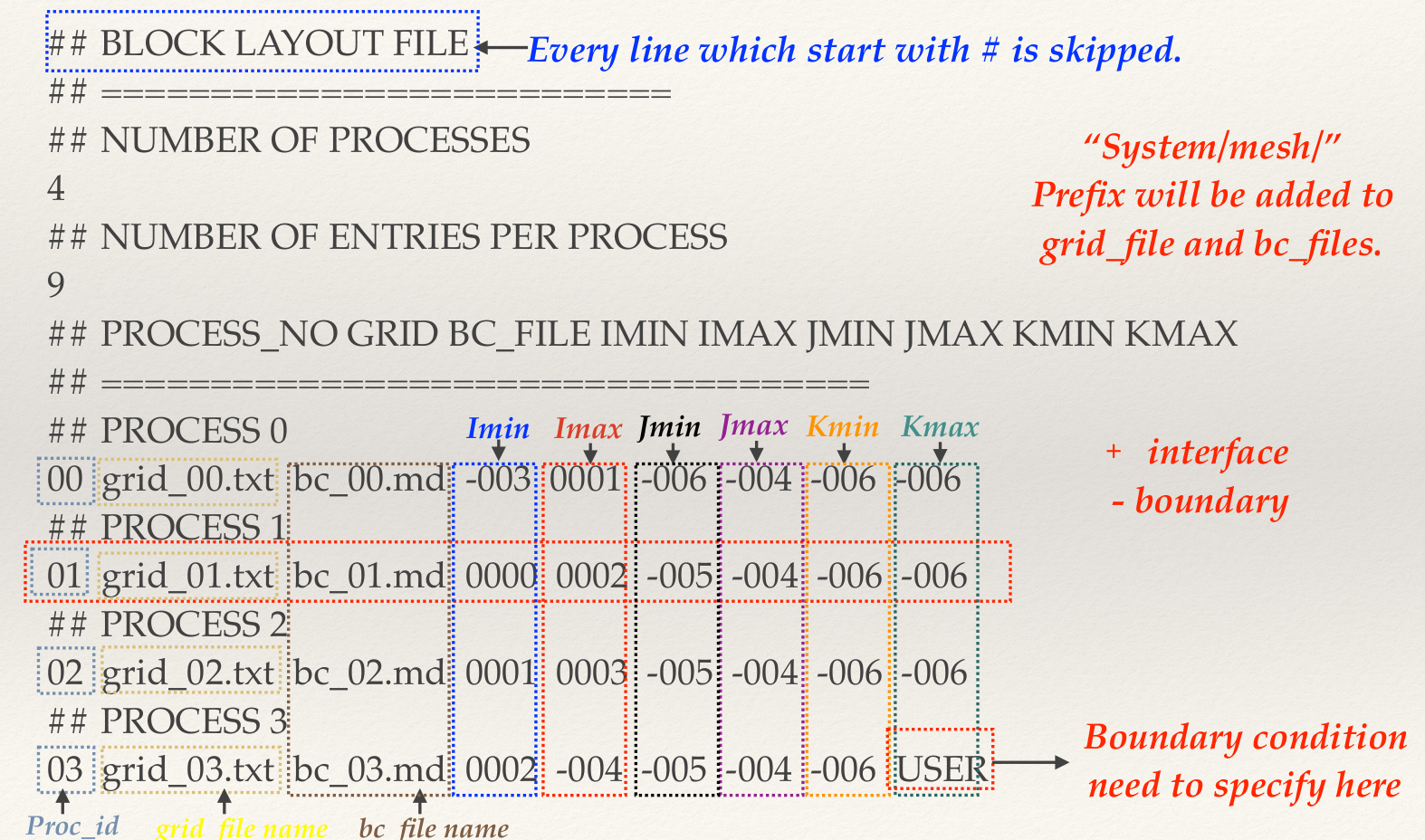
So for four blocks the layout file looks like following.
 ## BLOCK LAYOUT FILE
 ## ==========================
 ## NUMBER OF PROCESSES
 4
 ## NUMBER OF ENTRIES PER PROCESS
 9
 ## PROCESS_NO GRID BC_FILE IMIN IMAX JMIN JMAX KMIN KMAX
 ## ===================================
 ## PROCESS 0
 00  grid_00.txt  bc_00.md  -005  0001  -005  0002  -006  -006
 ## PROCESS 1
 01  grid_01.txt  bc_01.md  0000  -005  -005  0003  -006  -006
 ## PROCESS 2
 02  grid_02.txt  bc_02.md  -005  0003  0000  -003  -006  -006
 ## PROCESS 3
 03  grid_03.txt  bc_03.md  0002  -005  0001  -003  -006  -006
Each line starting with # is a comment line and hence will be ignored while reading.
The first non-comment line
state for how many blocks the layout file is written for and second line state how many entries
to read for each block. This number is same as the number of entries in the list above. After these two
lines, every non-comment line represents a block. The positive boundary condition at any face represents
the interface boundary condition, and the exact number represents the block number to which the current block
is connected through that face. The physical boundary conditions are listed below:
Boundary conditions
- -1: Supersonic Inlet
- -2: Supersonic Outflow
- -3: Subsonic Inflow
- -4: Subsonic Outflow
- -5: Wall
- -6: Symmetry or Slip-Wall
- -7: Pole
- -8: Far-field
- -9: Total inlet